

Hydraulic steering systems – features and types
Quality and reliability
MaviMare hydraulic steering systems represent a successful combination of superb craftsmanship and innovative technology to ensure the best possible performance under all situations. The quality is indisputably superior: all the products are in fact manufactured with corrosion-proof materials in order to guarantee a long durability and maximum reliability. The quick and precise response of the systems in all situations match a pleasant and smooth movement of the steering wheel. Finally, the absence of maintenance-free operationand the easy installation complete a series of advantages that the MaviMare steering systems offer all over the world.
Compact pump with a new design:
All the components of our hydraulic pumps are produced with the best quality of raw material which has been selected based on relating to the function of each component.
For that:
- The steering wheel shaft is made of stainless steel AISI 316.
- Cast iron rotor for greater durability.
- All pumps feature integrated non-return and pressure relief valves.
- Forged aluminum valve body: This feature eliminates leakage and provides greater strength in the threaded holes for the fittings.
- Dust seal and three different types of O-rings placed in three different positions, to provide greater prevention of the risk of leaks.
- Three different ball bearings to maximize pump efficiency.
- Four different surface treatments for enhanced durability and resistance of the external body of the pump.
- All the components of MAVIMARE pumps are obtained through an industrialized manufacturing process to ensure the best quality of the product.
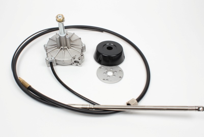
The hydraulic steering kits are supplied in a box complete with standard square bezel kit and hoses with fittings pressed on one end.
Hoses can be supplied to the required lenght, pre-fitted at bot ends and ready for installation.
Hydraulic steering systems – different applications
OUTBOARD HYDRAULIC STEERING SYSTEMS
| ENGINE HP UP TO | 80 HP | 150 HP | 300 HP | 350HP |
|---|---|---|---|---|
| SINGLE ENGINE | GF 90B | GF 150 GF 150R GF 150BR-01 GF 300R | GF 300HD GF 300BHD | GF 350HD |
| TWIN ENGINE (with counter rotating propeller) | GF 150BR-01 | GF 300HD GF 300BHD GF 300R | GF 300HD GF 300BHD GF 300R | GF 350HD |
SELECTION OF A OUTBOARD HYDRAULIC STEERING SYSTEM
For boats fitted with outboard motors, it is necessary to determine the maximum horse power developed by the engine.
For twin engines with same-direction rotation, add the power of both engines.
For twin engines working in counter-rotation, take into account the power of one motor only.
Examples:
| For the installation of 1 engine 200 HP | GF300HD/GF300BHD |
| For the installation of 2 engines 115 HP (same rotational direction) | GF300HD/GF300BHD |
| For the installation of 2 engines 200 HP (in counter rotation) | GF300HD/GF300BHD |
INBOARD HYDRAULIC STEERING SYSTEMS **
| BOAT LENGTH UP TO | 7 m 20 ft | 10 m 30 ft | 12 m 40 ft | 13,5 m 44 ft | 14 m 45 ft | 18 m 55 ft | 20 m 60 ft |
|---|---|---|---|---|---|---|---|
| SINGLE ENGINE (PLEASURE USE) | GE30 | GE50 | GE75 | GE75 | GE180 | GE350 | GE560 |
| SINGLE ENGINE (HEAVY DUTY) | GE30 | GE50 | GE75 | GE100 | GE180 | GE560 | GE560 |
| TWIN ENGINE (PLEASURE USE) | GE50 | GE50 | GE75 | GE100 | GE350 | GE560 | GE560 |
| TWIN ENGINE (HEAVY DUTY) | GE50 | GE75 | GE100 | GE100 | GE350 | GE560 | GE560 |
** The data shown in the table is for reference only, the choice of steering system selection must in any case be made based on actual torque calculations.
SELECTION OF AN INBOARD HYDRAULIC STEERING SYSTEM
For boats fitted with a rudder at speed up to 25 knots, the torque of the rudder or rudders is calculated according to the following formula and corrections.
Note that the torque required to steer a vessel depends on:
- The speed of the water flowing on the surface of the rudder at a certain angle ( not max speed).
- The rudder size.
- The total sweep of the rudder (and part of the boat), if the rudder shaft is not perpendicular.
- The compensating surface of the rudder.
Inboard hydraulic steering systems (Torque calculation formula)
Torque Calculation Formula for Speed below 25 Knots
Qr =A x [(0,4b) – e ] x V² x K
Qr = torque in kgm
A = total surface of rudder ( h x b ) in sqm
h = height of rudder in m.
b = width of rudder in m.
e = compensation width in m.
V = (maximum speed) of the boat in knots
K = coefficient according to total angle of rudder:
port to starboard 70° K = 15,89
port to starboard 80° K = 17,80
port to starboard 90° K = 19,52

Corrections in function of the type of boat
- for sailing boat Qr x 0,5
- for a boats with a steering nozzle Qr x 2.0
- for twin engine power boat with 1 rudder Qr x 0,5
- for boats fitted with multiple rudders (catamarans, trimarans, monohulls) multiply the calculated torque result by the number of rud ders fitted on the boat.
Once the torque is known, the appropriate cylinder is selected and one or two manuals pumps will be added accordingly.
Warning: selecting a pump with a higher displacement in order to reduce wheel turns , will require a larger-diameter steering wheel.
STERN DRIVE HYDRAULIC STEERING SYSTEMS
SELECTION OF STERN DRIVE HYDRAULIC STEERING SYSTEMS
| ARTICLE | STEERING CONFIGURATION | ENGINE MANUFACTURER |
|---|---|---|
| GF150ET GF150BET | Power assist | Mercruiser 1 Mercruiser Alpha I Mercruiser Bravo I Mercruiser Bravo II Mercruiser Bravo III Volvo 280 Volvo SX OMC COBRA OMC KING COBRA Yanmar |
| GF150BETX GF150ETX | Power assist | Volvo DP-E Volvo DP-S Volvo 290 |
| GF300BET | Without-power assist | Mercruiser 1 Mercruiser Alpha I Mercruiser Bravo I Mercruiser Bravo II Mercruiser Bravo III Volvo 280 Volvo 290 Volvo SX Volvo DPS |
| GE100 | Without-power assist | Volvo 275 |
| GF300BETX | Without-power assist | Volvo DP-E |